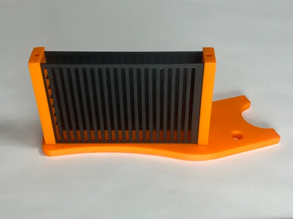
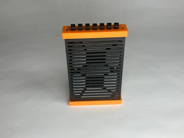
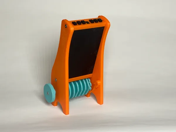
Slotted Mechanical Seven-Segment Display
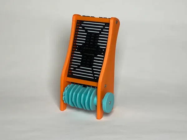
This is a demonstration model of a mechanical seven segment numeric display. It’s an open-source design that may be adapted for use in a clock, counter or other device. It may be built with any 3D printer.
How it Works
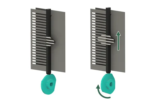
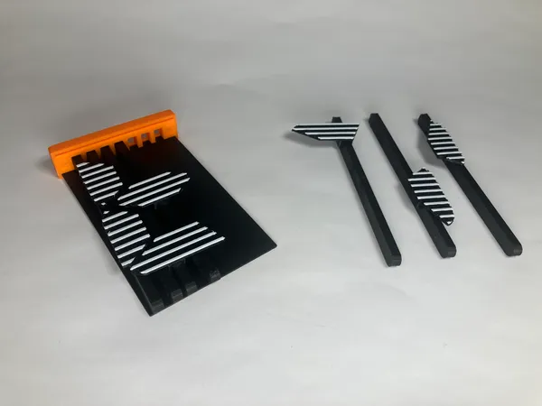
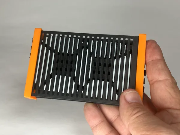
- The front face of the display features regularly spaced horizontal slots.
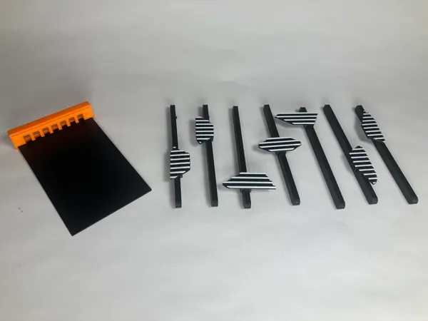
- Each segment is divided into horizontal stripes having the same spacing as the slots.
- A segment is turned on by shifting it upward to reveal the stripes, and turned off by shifing downward to hide them.
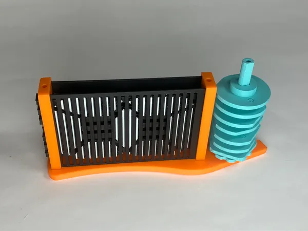
- The segments are shifted by a set of cams mounted on a common shaft.
Hiding and revealing an image through a slotted screen like this is nothing new. I don’t know what this mechanism is called, or if it even has a proper name. Please leave a comment (on Printables or Thingiverse) if you do.
I also couldn’t find any examples of its use in a seven-segment numerical display like this. Could it be that I’m the first? Again, leave a comment if you can point me to another!
Printed Spring

I decided to try a plastic spring detent to hold the camshaft in the right position for each digit. I had never modeled such a spring before.
To get the dimensions right, I modeled it the the extended position first, then used a bit of trigonometry to compute the equivalent length in its curved state.
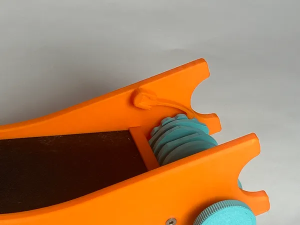
In real life, the spring does not quite extend to a straight line, but it’s close enough. The cam lobes have a 12° dwell angle, so there’s a bit of leeway in the detent position.
As for material, ordinary PLA seems to be working well, but I can’t answer for its longevity. I recommend you do not glue the spring in place. If it gets tired after a while, you can replace it, perhaps with different material or dimensions.
Printing
All the plastic parts are printed ordinary PLA. There’s no need to use support material.
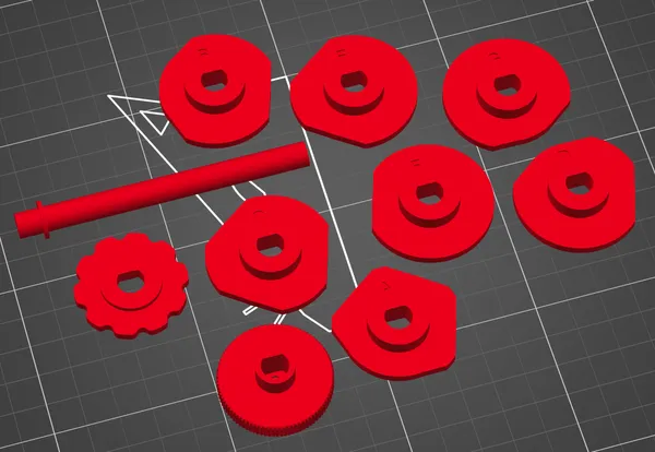
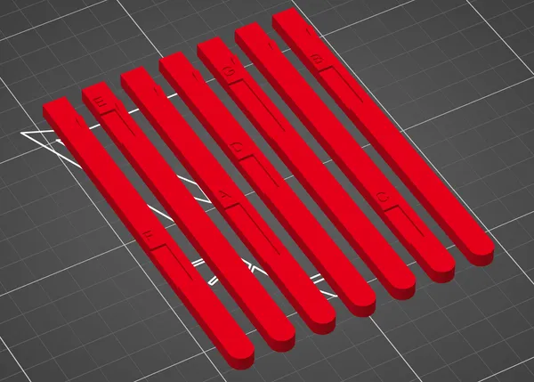
The cam parts and the knob should be oriented as shown here. Note that the camshaft has a flat side that should face the bed.
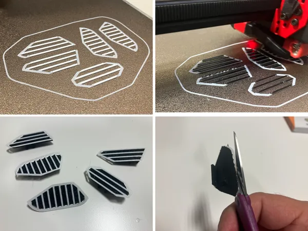
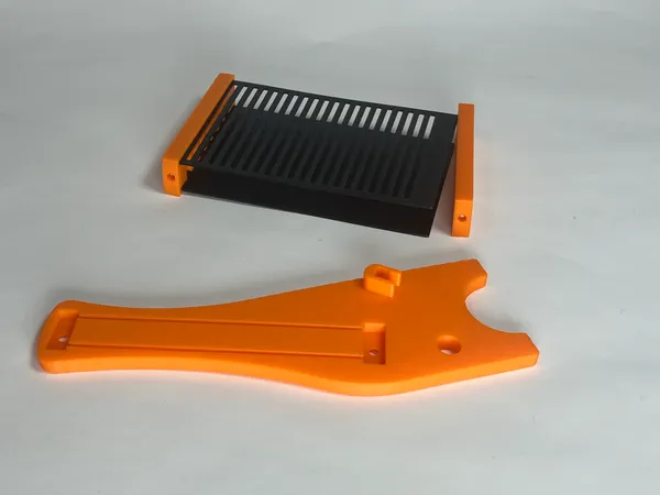
The segments are oriented with the striped part facing the bed. A pause to change color is added after 3-4 layers. These thin little stripes have an annoying tendency to detatch from the bed during printing, so I’ve added a sacrificial skirt to help anchor them.
This custom skirt is easier to remove than the auto-generated brim produced by the slicer. I found a small pair of scissors worked better than a hobby knife.
You could probably print the segments in a single color and apply some contrasting paint to the raised stripes, but I have not tried it. Don’t slop any paint into the channels between the stripes, or the effect will be ruined!
The jack pieces should be printed with the recesses and letters facing upward.
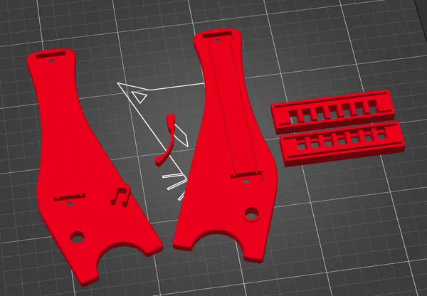
The remaining pieces should be oriented as illustrated above.
Assembly
Glue is required to fasten each segment to its jack. I use cyanoacrylate for PLA. Glue is not required or recommended anywhere else. You will need four M3 nuts, four M3x10 flathead screws and one M3x6 flathead screw.
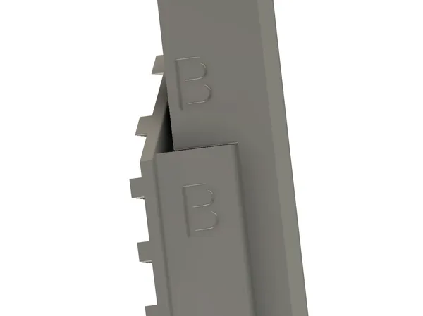
The segment parts are labeled A-G, from left to right to match the cams. Glue each segment to its jack, matching up the letters as shown.
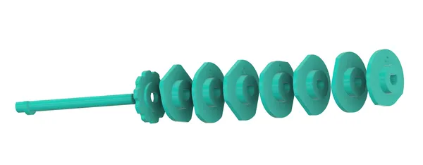
The cams should be added to the shaft starting with the detent wheel, then in alphabetical order. Simply slip them onto the shaft; there’s no need for glue.
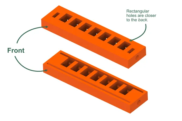
The top and bottom parts are identical, but must be arranged as shown, with the rectangular holes closer to the back of the mechanism.
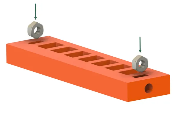
Press the nuts into their slots. They should be a snug fit, and should end up with their hole aligned with the hole in the plastic.
Before going further, test fit each jack in its hole in the top and bottom pieces. The jacks should slide freely with no binding. The mechanism relies on gravity to return the jack/segment assemblies to the lower position, so take your time with this step. Trim any blobs or elephant foot from the jacks if necessary.
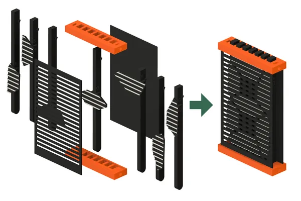
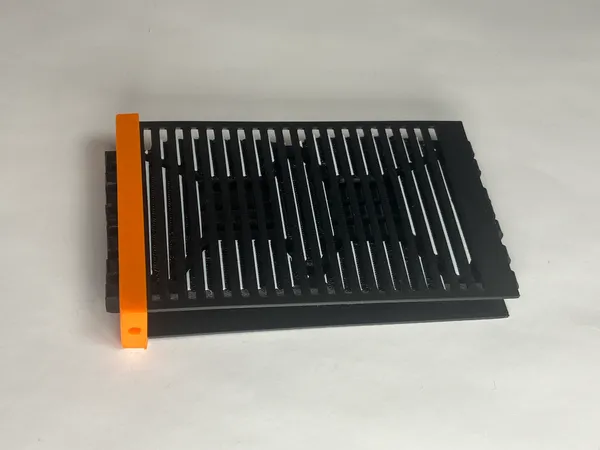
Before adding the jacks or cams, test fit the rest of the assembly as shown above. First slide front and back plates into the top and bottom pieces. Then fit the sides in position. A slightly snug fit is okay, but you shouldn’t have to force anything. Then disassemble again.
This final stage of assembly is a good opportunity to cultivate patience! After some experimentation I think the following procedure works best.
Arrange the jacks and segments in order, and slide the back piece into the top piece. Note the orientation as discussed above.
Now add the jacks in order. Note that the jacks slide beneath the segments of their neighbors.
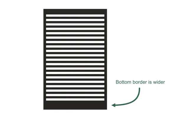
Examine the slotted front piece, and notice that the border section is wider at one end. This end goes toward the bottom. Carefully slide it in place. This piece has a maddening tendency to catch on the raised stripes of the segments, so take your time. (This annoyance will not be a problem once fully assembled.)
For this step, I’ve found it easiest to turn the assembly on its end as shown (upside down). Then, thread the curved ends of the jacks into the bottom piece, and slide it onto the slotted front and solid rear plates.
In the next few steps, try not to let the jacks slip out the lower end. Keep them in position as shown.
Insert this entire assembly into the left side piece. This side has the mount for the detent spring. Add the camshaft as well, with the longer end upward.
Add the right side piece.
While holding the machine together with your fingers, turn the cam and test operation. It should be easy to turn, and the jacks should all dance up and down without binding. If anything sticks, locate the source of the trouble and correct it before proceeding.
When satisfied, add the four M3x10 screws.
The knob may stay on the shaft just fine with friction fit. If not, the small M3 screw may be added. This will form threads directly into the plastic, so don’t overtighten!.
Carefully extend the detent spring, and insert it into its mounting slot. I’ve found that friction alone holds the spring in place, and recommend you leave it so (as noted above).
Source Files
You can get the 3MF, STEP and Fusion 360 files from any of the the links below.
Taking it Further
There’s a lot of scope for experimenting with this idea.
I originally planned to build a clock based on this mechanism, but thought it prudent to test the basic idea first. If you use the idea in your own project, please share your results. Maybe you can get a clock working before I do!
More densely spaced slots might look better, though that might make the segments a bit more challenging to print.
I made the stripes on the segment raised so that I could conveniently print in two colors with a single-material printer. If you have a multi-material printer, you could model the stripes and dark background in the same plane. This would make it slightly easier to assemble, as the stripes would not catch in the slotted front plate.
It might look better printed with dark segments on a light background. If you try this out before I do, please share a photograph!
If the spring detent is removed, you can quickly spin the knob to your desired digit. The intervening digits fly by in a blur, reminiscent of a split-flap display. The mechanism need not be confined to a sequential counter or clock.
The idea should be adaptable to laser cutting as well. It does not rely on any complex 3D geometry.
Search for images using the terms “seven segment display” or “seven segment lcd”, and look closely at the segment shapes. You’ll see that there’s quite a bit of variation. On mine the segments are asymmetric; the right vertical segments are slightly taller than the left. I like the way this looks, but maybe you’ll have a better idea.
My cams have just ten positions to represent digits, but a lot of other characters are possible as well. Search “letters on seven segment display” for ideas. Adding more positions will require larger cams, in which case it might make sense to mount them behind the digits. I envision the cams bearing upon rocker arms that lift and lower the jacks.
But, why stop there? How about a fourteen-segment alpha-numeric display? This would be an ambitious project requiring more closely spaced jacks and much larger cams. I’d love to see it!
I hope you enjoy the project!