MIDI Foot Controller

I recently dug my guitar out of storage and started playing again after a 40-year hiatus. Boy, I’m out of practice!
To make matters worse, there’s a lot of new tech to brush up on! Among other things, a phone or tablet can now simulate the sounds of the old amplifiers and effects pedals.
But you still need to change settings, sometimes even in the middle of a song. That’s where this project comes in. It speaks MIDI 1.0 over a USB Transport so it should be compatible with most music software, and many instruments as well.
This accessory has three foot buttons with a multi-color LED for each. There are no knobs or other controls. If you need more, the software supports as many buttons as you like, up to the limits of your microcontroller board.
I built mine for less than $20, but I already had some of the necessary components. If you’d like to build your own, read on. It’s all open-source, so you may customize to your heart’s content.
How It Works
It’s a MIDI device, but it does not send Note On/Off messages like a MIDI keyboard. It sends only Control Change and Program Change messages, which are used to control ancillary functions of your instrument or software.
Each button can behave in one of three ways:
Momentary
Sends a Control Change message with a value of 127 when pressed; 0 when released. The LED lights up only while the button is depressed.
Toggle
Pressing once toggles the LED on and sends a Control Change message with a value of 127. The next press toggles the LED off and sends a value of 0.
Program Change
Cycles through a number of programs. Each press sends a Bank Switch message followed by a Program Change message. The bank, number of programs, and first program are configurable. A different LED color is displayed for each program.
More than one Program Change button may be configured. If so, only the last one pressed is active; the LEDs for the others are turned off. Each Program Change button should be configured to use a different bank or program range.
The Circuit
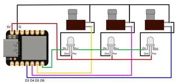
The circuit is quite simple. The buttons are each wired to their own input pin. The LEDs are wired in a chain controlled by a single output pin. It’s a good practice to add a .1µf capacitor across the power leads at each LED, but with just three it seems to be unnecessary. Add them if you like.
Bill of Materials
| Quantity | Item |
|---|---|
| 1 | Seeed Studio XIAO development board |
| 3 | SPST momentary contact footswitches (see below) * |
| 3 | WS2812 or equivalent addressable RGB LEDs, 5mm * |
| 3 | .1µf ceramic capacitors (optional I think) * |
| 4 | M3x10 flat head screws for bottom cover |
| 1 | M3x10 cap screw for circuit-board clamp |
| 5 | M3 hex nuts |
| ~ 2m | 28 AWG (or similar) hookup wire |
| ~ 20cm | heat shrink tubing sized to match your hookup wire |
| 4 | stick-on rubber feet |
| a dab | hot glue, if necessary, to hold the LEDs in place |
| 2 | small zip ties * |
| ~ 120g | 3d print filament |
* +1 for each additional button
Get the Correct Buttons
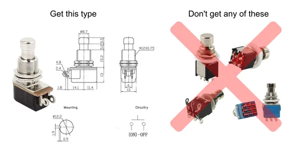
This project uses SPST momentary-contact buttons. These are not the same as the latching type found in the original effects pedals. Be sure to get the right kind! The kind we need has just two pins; not six or nine.
Also note the dimensions. The case is designed for this long-thread type. Fortunately they seem to be the most common size. They also allow for a thicker case, which probably makes the pedal more robust.
XIAO Notes
I chose the SAMD21 version of the Seeed Studio XIAO developent board for this project. It’s compact and offers a lot of capability for the money.
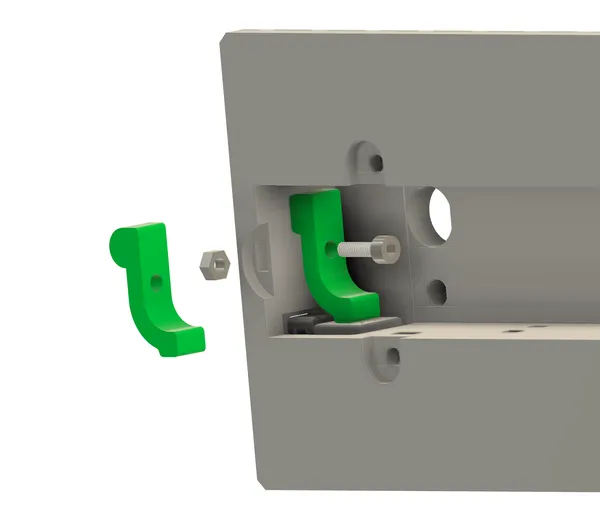
Like many compact boards, the XIAO has no provision for mounting. The clamp arrangement I’ve come up with seems to be working well so far. Fasten it nice and tight, but not so tight that you crush the metal shield.
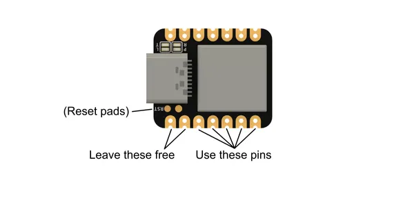
The SAMD21 XIAO has two small pads next to the USB jack, used to force the device into bootloader mode. Should the need arise, you’ll have to short these together with a paperclip or small piece of wire. This will be easier to do if you avoid using the nearby D0 and D1 pins. I used pins D3 through D6 for this project.
Know Your LEDs
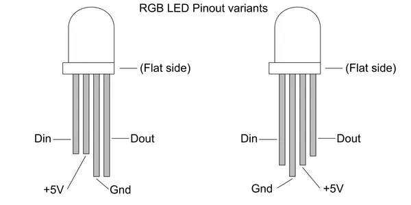
Some WS2812-compatible LEDs have the leads in a different order than others. They’re both fine; you just need to know what kind you have. Mine happen to be the type on the right. If you can, test yours on a breadboard to be sure.
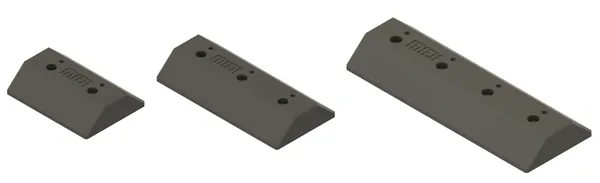
The 3D models are available at the following links:
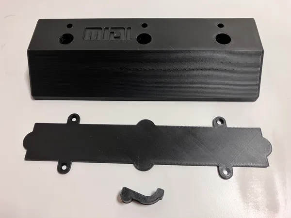
Decide how many buttons you want and print the corresponding parts. There are just three parts to print; the main case, the bottom cover, and a small clamping piece that holds the microcontroller board in place. I used PLA for everything with light infill and just three perimeters. Don’t get carried away with the print density; this case is quite robust.
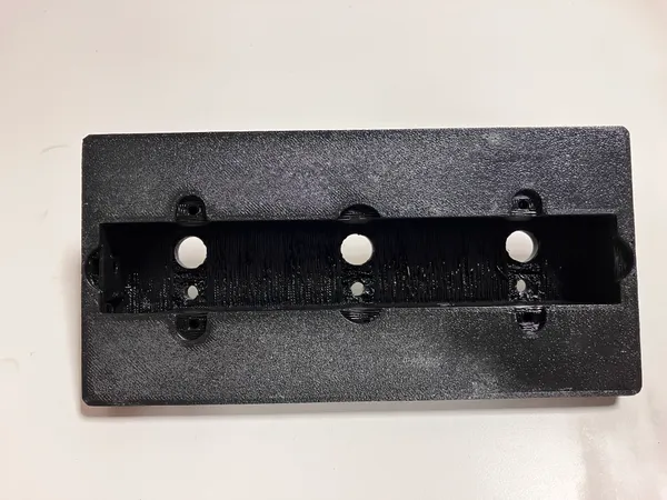
The main case has holes piercing the top for the buttons and LEDs. I modeled small indented areas next to these holes. This helps eliminate the need for support material. If your printer’s bridging is not tuned perfectly, you may have to trim a few stray hairs.
Open the Project and Configure
The source code for this project is here on Github. Clone the project with git, or download the zip file and unpack to your computer.
The project is set up for use with the PlatformIO IDE. Opening the project should automatically load the correct library files listed in platformio.ini.
In main.c, look for NUM_BUTTONS and set it to the number of buttons you have.
#define NUM_BUTTONS 3
.
.
.
#define LED_PIN D6
const uint8_t button_pins[NUM_BUTTONS] = {D5, D4, D3};
config cfg = {
    midi_channel: 2,
    vee: 64,
    buttons: {
      {btype: SWITCH_PC, {pc:{n_progs: 6, bank: 2, first_prog: 0}}},
      {btype: TOGGLE_CC,  {cc:{code: 80, hue: FP_HUE_AQUA}}},
      {btype: MOMENTARY_CC, {cc:{code: 81, hue: FP_HUE_ORANGE}}}
    }
};
Find an array called: buttons. Each entry in this array configures a single button. The allowed values are described in detail in code comments, but they follow the same ideas outlined above under How it Works. The default code contains an example of each button type.
Most of the configuration can be changed later via the Web MIDI tool (see below). The pin assignments and NUM_BUTTONS identifier must be defined in the source code.
Program the XIAO board before assembling; it’s easiest when the board is outside the case. More information about this board is available at Seeed’s Getting Started page. They also have a page about PlatformIO.
Can I Just Use the Arduino IDE?
You may be able to, but it will be a bit of extra work. This project uses the Arduino platform and library files, so it is mostly compatible with the Arduino IDE.
I had to override a few build variables including build.usb_product which indirectly defines the MIDI device name. In PlatformIO, this is done via an extra_script specifier that doctors-up the build flags. In this project, it’s called change_usb.py, in case you’d like to have a look.
When using the Arduino IDE, it appears that this must be done by directly editing the boards.txt file, which is buried down in the bowels of the library packages. This is not something I want to encourage. Putting project-specific settings in a global configuration file just seems like a very fragile technique that’s bound to cause headaches. If you’re an Arduino expert, perhaps you have a better idea!
Get Organized and Solder
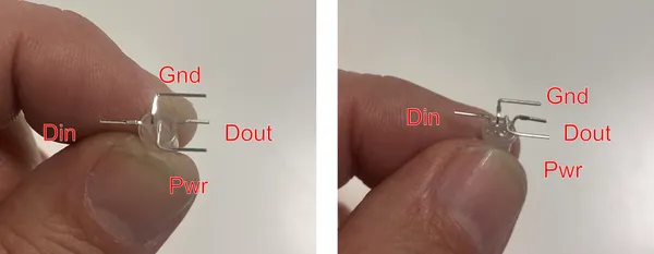
I find it easiest to bend and trim the LED leads as shown. (Remember that your LEDs may be different!).
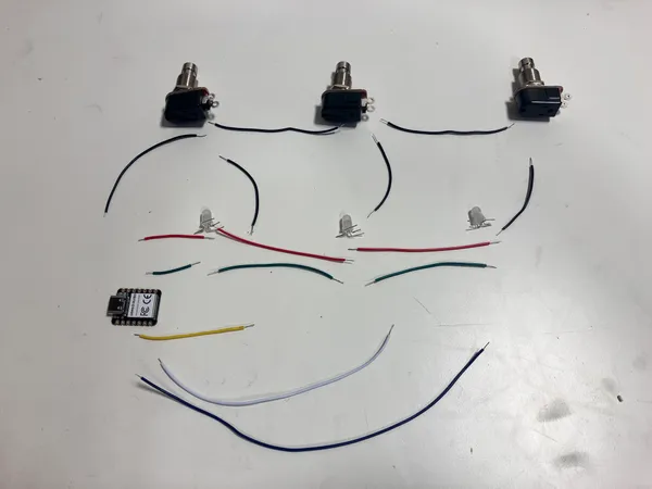
I also like to cut the wires to length, strip the insulation and lay everything out beforehand. I added heat shrink only on the LED joints; the button lugs are far enough apart that I didn’t think there was much risk of a short.
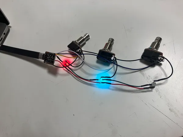
Once it’s all soldered together, carefully test everything while it’s still outside the case.
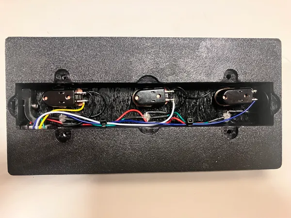
Then, gently put the components into the case, starting with the circuit board. There are channels in the side wall to accept zip ties to hold the wires in place.
Finish up
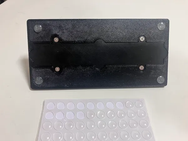
Slide the nuts into the slots, and fasten the cover on with countersunk screws. On mine, the slots were a bit too loose and the nuts had a maddening tendency to rattle free before I got the cover screwed on. Rather than reprinting, I just used a few dabs of hot glue to hold the nuts in place.
I had some rubber feet left over from a prior project. These are definitely recommended. Otherwise the pedal tends to skate all over the floor.
Verify With a Test Utility
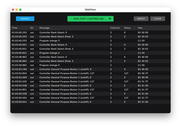
There are a number of MIDI development tools that can be used to verify that the controller is operating properly. It’s a worthwhile step that may save some frustration later.
I’ve tried out two of them: MidiView, pictured above, and MidiMonitor. Both of these worked fine for me.
Install either tool; plug in the foot controller and press some buttons. You should see the corresponding MIDI messages scroll by. Whether it’s working properly should be obvious, but consult the MIDI spec if you need more detail.
If you don’t see any messages, or see the wrong ones, stop and troubleshoot. Try recompiling and reloading, and take careful note of any error or warning messages. A full treatise on debugging is beyond the scope of this article, but there are many good resources on the web.
The Web MIDI Configuration Utility
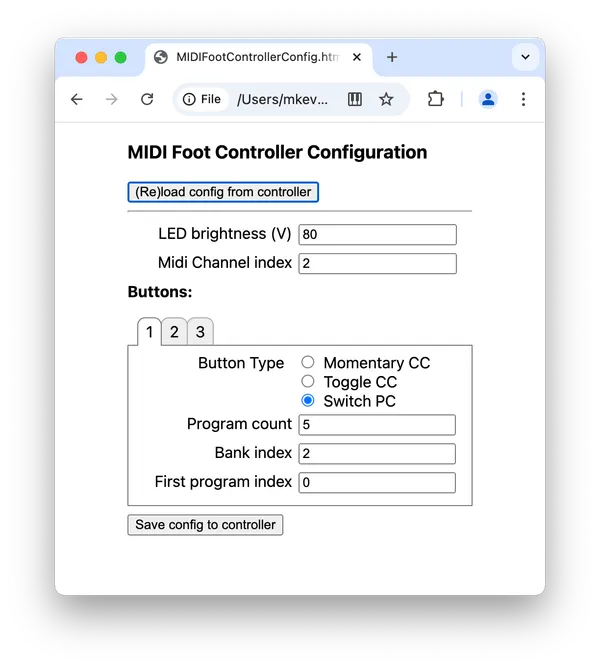
I’ve written a configuration utility using the Web MIDI API. This API allows access to MIDI devices from a web browser. The entire utility is contained in a single file: MIDIFootControllerConfig.html, available in the GitHub project linked above. Open it in a web browser on a computer attached to the controller. The interface should be self-explanatory.
Unfortunately Web MIDI is not consistently implemented by all web browsers. I had good luck with Google Chrome. I have not figured out how to load the file onto a mobile device, nor do I know whether any mobile browser works with Web MIDI. I’ve only been able to test with OSX.
Note that NUM_BUTTONS can only be set in the source code, so be sure to set that up when you program the device. Also note that use of this utility is entirely optional. You can always adjust your configuration in the source code as described above. If you need to make frequent changes, this utility may be more convenient.
Configure Your Target Software or Instrument
You’re mostly on your own here, since I can’t cover all variations. Connecting and using a MIDI device should be covered in your software or instrument’s user manual. There is one nasty gotcha you should know about:
Off by One!
There’s an annoying issue with MIDI insruments and software.
Computer programs generally count things starting at zero. If you have three items to keep track of, they’re referred to as item 0, item 1, and item 2. Human beings more naturally assign the values 1, 2, and 3.
Unfortunately MIDI instruments and software are not entirely consistent in this respect. Sometimes the first selection is 0; sometimes it’s 1.
The MIDI channel number seems to be consistently 1-16. But Control Change, Bank Switch, and Program Change numbers often start at 0. These are the conventions I’ve adopted with the configuration of the MIDI Foot Controller.
This means you may have to do some experimenting to see how your software or instrument interprets the buttons, and you might end up having to add or subtract 1 somewhere to make them align. I’m sorry about that, but no matter what convention I adopt it will look wrong to somebody. The best I can do is to aim for an average.
My “Rig”
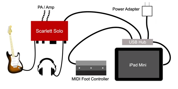
For the curious, here’s a bit more about the rig I currently use. It’s an iPad Mini, plugged into a Scarlett Solo Audio/USB interface, via a USB hub. The MIDI pedal is plugged into this USB hub.
The hub must support pass-through charging. It’s necessary even without the pedal, as otherwise the audio interface would draw the iPad’s battery down very quickly.
For a while, I used my iPhone SE. This works just as well, but requires an extra “camera adapter” if it is an older-style phone with a Lightning jack instead of _USB-C.
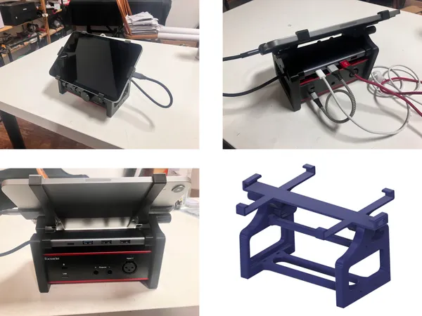
Since that’s a lot of parts to rattle around, I made a little 3D-printed rack to hold the whole thing together. I have not published this, as it’s quite customized to my particular hardware. Let me know on Thingiverse or Printables if you’d like to see it.
For software, I’m using an app called ToneStack Pro which is a real bargain at just $9.99. The basics you get for the base price are enough to get anyone started.
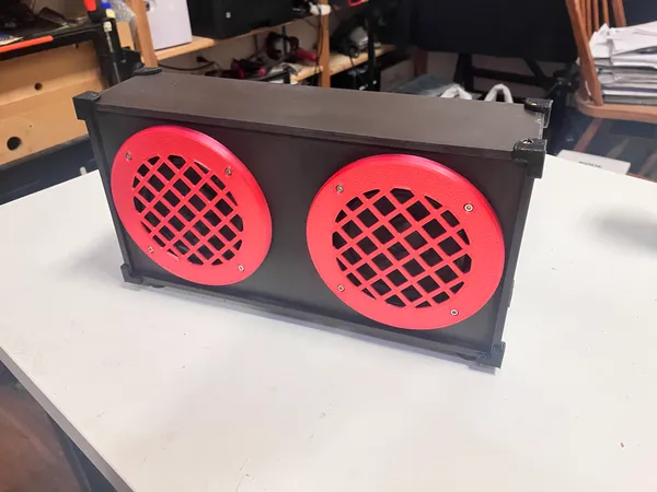
I usually practice with headphones plugged into the Scarlett, but I also made a small “amplifier.” It’s just a pair of 4" speakers plugged into a stereo amplifer board found on Amazon, all mounted in a plywood case. I can plug the Scarlett directly into this if I don’t feel like using the headphones.
This amp would never do for a real performance, but it sounds much better than it has any right to for the money invested (about $40.00). For performance, I could theoretically plug the Scarlett outputs directly into a PA system, but I haven’t tried that yet.
Taking It Further
Naturally there is plenty of scope for altering and improving this thing. I’m constantly coming up with new ideas, and always have to restrain myself in the name of simply getting it done. Here are a few of my thoughts.
More Buttons
Yes, I know… More! More! More! This is why I made it easy to add buttons in the software.
But be honest with yourself before you rush in and build a device with three dozen buttons. More isn’t always better.
First of all, your toes must have the dexterity to press the right button without accidentally pressing two. This means you can’t place the buttons too close together, so more buttons requires a larger device.
The biggest problem is that you have to remember what all those buttons do! You could label them of course, but that might not work well on a dimly-lit stage.
At some point it’s simply easier to adjust the setting on your iPad or instrument. I think that point is reached after four buttons.
Different Case
I’ve included the CAD model if you want to try changing the size, or maybe just adjust the æsthetic. The entire project is open source, so have fun!
You could also use an off-the-shelf project case. You’ll have to figure out how to mount the XIAO board so that the USB port is accessible yet not too fragile.
Blink States or Numeric LED
The Program Change button type selects LED colors automatically, dividing the color space up into however many programs you’ve configured. If you have 3 programs it chooses red, green and blue; with 6 programs you get red, yellow, green, cyan, blue and pink. It will still work with more than this, but it becomes increasingly difficult to distinguish the colors. If you have 12 programs, I think it’s better to configure two buttons with 6 programs each.
If we added Solid, Slow Blink, and Fast Blink options, we could easily distinguish three times as many options with a single button.
But, that’s a lot of toe tapping to get to the program you want. And, you have to remember the program associated with every blink and color combination.
We could also add a numeric or alphanumeric display. Maybe we use a single centrally-mounted display, or maybe a small one for each button. But, now things are getting more complicated, and I’m not really sure we’ve improved the user experience.
I keep coming back to the question, “Just how will someone really use this thing?” …and I keep concluding that simpler is better.
Add Knobs
Adding a simple potentiometer would be straightforward technically, though it does require an input pin for each. When the value changes, scale to range: 0 to 127 and send a CC message. If you want finer control, you can use 14 bits for the first 32 CC messages. Scale to range 0 to 16383; then send two messages: MSB followed by the corresponding LSB message.
I have the same objection here as mentioned a few times above: it’s probably easier to tweak a setting on your iPad or instrument than to squat down and adjust a knob on the pedal.
I think this would only make sense if you really want to replicate the exact experience of the original pedals. If that’s your goal, go for it!
Use a Different Microcontroller
I’m sure this project can be adapted to a lot of microcontroller boards. It might require minor changes to the firmware, but the biggest change would be the board mount arrangement. The board must include a USB port and must support the libraries listed in platformio.ini.
Go Wireless
Many development boards support Bluetooth or the newer BLE. Seeed Studio has eight in the same inexpensive XIAO form factor. While this eliminates a wire you might trip over, it adds the hassle of having extra batteries or maybe a charging cord. Ironically, you might end up dragging more stuff to your gig to support a wireless device.
Nonetheless, it’s an intriguing thing I’d like to look into. At present, the USB jack is probably the weakest point on this device. Stepping on the wire where it enters the case is liable to do some damage.
There’s really no excuse not to explore the idea, since several of the XIAO boards mentioned even have charging circuitry built in. The current board mount should work without modification; I just have to hollow out some space for a battery. I have a few of these boards on order so stay tuned for an update!
Feedback
I hope you’ve enjoyed this article. If you build the project, or have any thoughts or questions please let me know in a comment at Printables or Thingiverse.