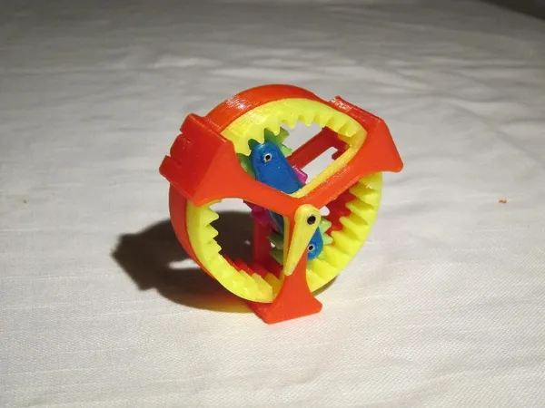
High Reduction Ratio Planetary Drive, Revisited
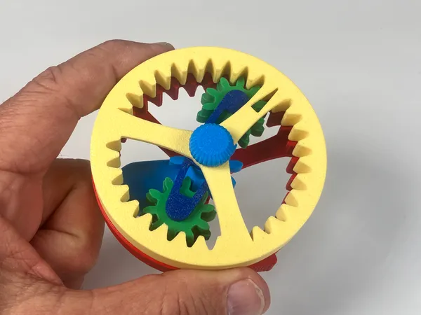
The original version of this planetary gear model was one of the first printable designs I published, just about twelve years ago. It was a featured upload on Thingiverse for a short while, and inspired a lot of interesting feedback. It was a fun project, but I always felt that if it had been easier to assemble it would be accessible to a larger audience.
Back then I used rather primitive modeling tools, which made alterations difficult and time consuming. Now that I have proper 3D CAD software and a bit more experience, I thought I’d revisit this project and see if I couldn’t improve upon it.
This new version:
- is entirely 3D printed
- requires no additional hardware
- requires no tools to assemble
- has a few optional components
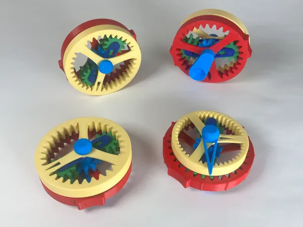
- and features four basic variants:
- The original at 64:1
- A reverse-turning -56:1
- A lower ratio of 12:1
- A very high ratio of 148:1
The original video also included a cursory explanation of how the gear ratio is computed, but wasn’t comprehensive. We’ll work this out in more detail below.
Printing
Everything prints without support material. The mesh files are in the recommended orientation for printing. Ordinary PLA is fine.
I recommend 3 or 4 perimeters, 15% infill, and ordinary .2mm layer height. If your printer is not perfectly tuned, it may be a good idea to print the crank part by itself to minimize any blobs on the axle and threads.
Assembly
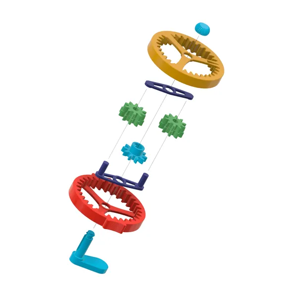
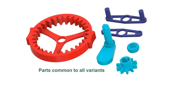
The basic assembly is straightforward; just follow the exploded view. Everything is secured with a single thumb nut.
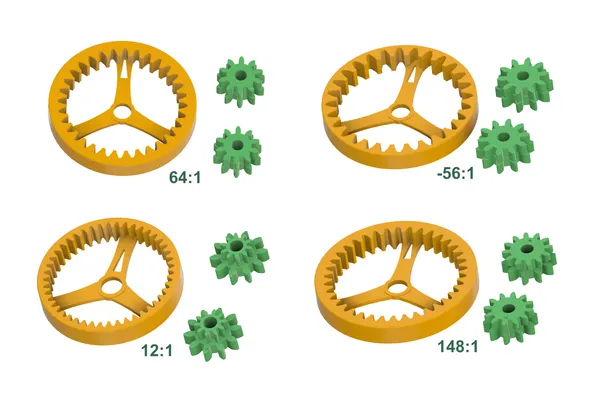
The variants use different planet and driven ring gears. The remainder of the parts are the same, however the planet gears are arranged a bit differently.
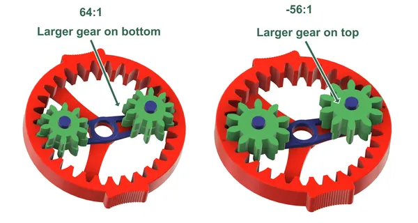
The 64:1 variant has identical planet gears, situated with the larger part down. Print two planet gears.
The -56:1 variant also has identical planet gears (though different from the 64:1 variant). These are situated with the larger part up. Again, print two planet gears.
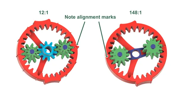
The 148:1 and 12:1 variants each have two different planet gears. Print one of each. The planets have witness marks on the top of the gears; one circle, one triangle. These must be aligned with the matching marks on the fixed ring.
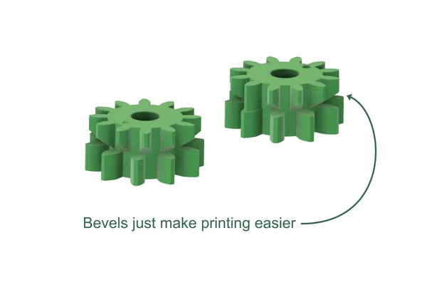
Note that the upper teeth on the 148:1 planet gears overhang the lower teeth in spots. The undersides are beveled where necessary, simply to allow printing without support material. This does does not affect the operation of the gear in any way.
Optional Parts
There are two alternate components:
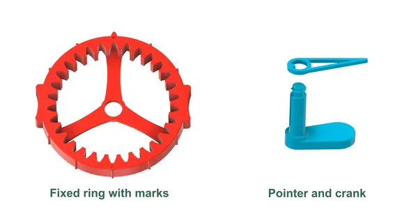
The fixed ring has external marks every 30 degrees. One larger mark indicates the starting position.
The front-mounted pointer indicates the input crank position, and requires a slightly longer crank.
These may be used with any of the gear sets, but are especially useful with the 12:1 set. The marks can then represent hours, the larger mark being 12 o’clock. When assembling, take care to align this pointer and the indicator in the driven ring at their 12 o’clock positions (see the 12:1 image above under Assembly).
TL;DR The remainder of this post discusses technical detail, and is not necessary if you just want to build the model and enjoy it.
How It Works, Intuitively
The 64:1 verison easiest to understand. The fixed ring has 30 teeth, and the driven ring has 32. Note that two opposing teeth on each ring are kept aligned by the meshing planets. As the carrier revolves, this alignment point moves along with it.
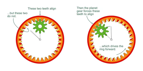
Since there are more teeth in the driven gear, it must advance as the carrier turns, to keep the opposing teeth aligned. In this case it advances two teeth (1/16th of a turn) for each turn of the carrier. This, multiplied by the input-to-carrier ratio of 4:1 gives 64:1. This is the simplified explanation I offered in the original video.
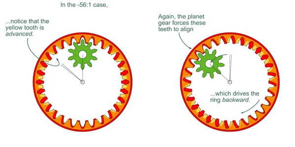
The -56:1 variant is similar. With only 28 teeth in the driven ring, it must reverse by two teeth (-1/14), per carrier-turn. This, with the 4:1 input-to-carrier ratio gives -56:1.
Things get a bit more complicated if the rings differ more substantially and/or the upper and lower segments of the planet have different numbers of teeth. A more general formula is derived below, but first we should talk about pitch, and in order to do that we should define a few terms.
Terms
| Symbol | Meaning |
|---|---|
| number of sun gear teeth (the driver) | |
| number of fixed ring teeth | |
| number of driven ring teeth | |
| number of teeth in planet portion meshing with sun and fixed ring | |
| number of teeth in planet portion meshing with driven ring | |
| rotations of planet (about its own axis) | |
| rotations of sun | |
| rotations of carrier | |
| rotations of driven ring |
Also, let’s consider positive rotations to be counter-clockwise or forward, and negatives to be clockwise or backward.
Gear Pitch
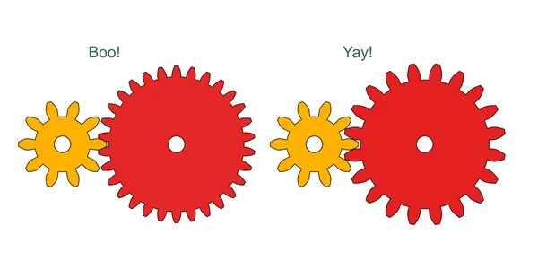
Obviously a gear having big teeth won’t mesh with a gear having small teeth; the teeth must be the same size. We can think of pitch as simply the size of a gear tooth.[1] Note that pitch is not the number of teeth, but the size of a single tooth.
For these models:
- The sun, fixed ring and lower portion of the planet must be the same pitch.
- The driven ring and upper portion of the planet must be the same pitch.
But these two layers need not be the same pitch. Note that the driven ring never meshes with the sun gear or lower half of the planet.
In fact, we usually have to alter the pitch for one or the other of these layers. Consider our 12:1 model:
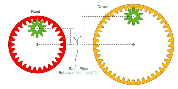
If we tried to make these two layers the same pitch, the two parts of the planet gear could not be joined since they are at different center distances.
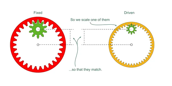
We solve the problem by scaling the driven ring layer so that these distances are the same. Since we do not want to alter the tooth count, we must scale the size of the teeth (pitch) as well as the overall size of the gears.
The difference in pitch is given by this formula:
We Can Sometimes Cheat
Note that for the 64:1 case, the factor works out to 10/11. At the size of these gears, the resulting change in pitch radius is only about 1mm. Since the tooth count is the same for both planet layers, we could dispense with the stepped planet gear, as long as we add a bit of extra clearance.
My first version, twelve years ago, took this approach and worked fine. This display model has very loose tolerances, so there’s no noticeable difference.
But, it’s really not much more difficult to make the gears properly, so this new version is designed with the correct pitch in each case. I think it makes the operation of the mechanism easier to understand; which, after all, is the whole reason for this model’s existence.
Deriving the Generalized Ratio Formula
On with the math. For a compound gear train like this, I find it easiest to tackle the problem in stages.
The task is to find s when d=1.
To begin with let’s consider what happens to the planet gear during one rotation of the carrier (c = 1). It should be easy enough to see that:
Note the minus sign, since the planet turns backwards with respect to the carrier.
Now for the sun gear. If the carrier were stationary, the sun’s rotation would simply be:
But, since the planet is mounted on a moving carrier, note what happens:
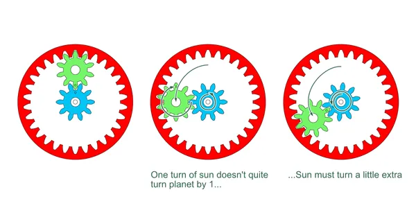
In order to rotate the planet once about its own axis, we must turn the sun a bit extra to account for the rotation of the carrier. Since we’re considering just a single rotation of the carrier, we simply add one:
Now we can substitute our step 1 result for p and simplify:
Remember, this formula describes rotations of sun gear to give one rotation of the carrier.
Since we’ve already figured out the planet turns, the driven ring should be easy. Let’s again consider the carrier to be stationary. We can relate the driven ring to the planet like so:
Since the carrer does turn once, we add 1 to get the actual rotation of the driven ring:
Substituting our step 1 formula for p we get:
Now we have one formula that relates sun to carrier (step 6), and another that relates driven to carrier (step 9). Remember, we’ve been assuming the carrier rotation to be one for simplicity’s sake. The complete expressions are:
So, solving each of these for
Now, we can set the two equal, plug in 1 for d, and solve for s:
This table has the tooth counts and ratios worked out for each variant:
| Ratio | |||||
|---|---|---|---|---|---|
| 10 | 30 | 10 | 10 | 32 | 64:1 |
| 10 | 30 | 10 | 10 | 28 | -56:1 |
| 10 | 30 | 10 | 12 | 37 | 148:1 |
| 10 | 30 | 10 | 10 | 45 | 12:1 |
Try it yourself to double-check my work!
…Or You Could Just Look it Up
If that was entirely too painful, have a look at the following page. They have worked out the formulae for this and many other planetary drive variants.
Our models are depicted in their figure 15. The sun:carrier ratio we solved in step 6 is their figure 12. They use different symbols, but the formulae are equivalent to ours.
Download and Experiment!
The mesh, STEP, and Fusion 360 files are available on the following sites as usual. Please post comments there if you make your own or have questions.
Original Project
Here are links to the original project and video for completeness’ sake.
Pitch is more precisely defined as either (diameter/tooth count) or (circumference/tooth count) ↩︎