Cycloidal Gears for Fusion 360
Traditional clockmakers use gears having a cycloidal tooth profile. This is an older gear type, no longer in widespread use.
These days involute profile gears are much more popular for a number of reasons, including:
- They’re easily manufactured via a technique called hobbing, so they’re widely available.
- They tolerate slight variations in the distance between centers.
- Their teeth are formed the same way for both members of a pair.
Some feel that that the older cycloidal profile is still a better choice for clocks, though the debate is far from settled. I wrote this add-in to explore the subject for myself, and I invite you to do the same.
Developing the Profile
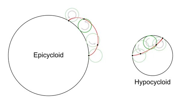
A meshing pair of cycloidal gears has teeth derived from two kinds of curve:
- an epicycloid, formed by rolling a circle outside the pitch circle of one gear.
- a hypocycloid, formed by rolling a circle inside the pitch circle of the other.
The pitch circles may be different sizes, but the generating circle must be the same in order for the teeth to mesh properly.
The curves are then trimmed, mirrored, and radially duplicated to form the gear teeth. Note that the contacting surfaces of the epicycloid gear lie outside its pitch circle, while those of the hypocycloid gear lie inside.
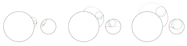
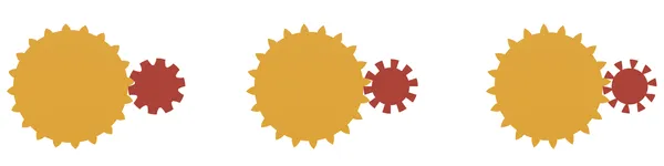
The generating circle can theoretically be any size up to the size of the hypocycloid gear’s pitch circle. At smaller sizes, the epicycloid teeth become very small; at larger sizes the hypocycloid teeth become undercut. The sweet spot seems to be exactly half the diameter of the hypocycloid gear’s pitch circle. As a bonus, the hypocycloid curve then simplifies to a straight line. This is the size recommended by all the literature I’ve seen, and the add-in enforces it.
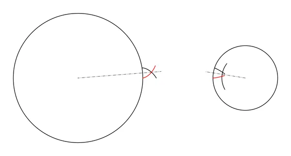
Theoretically we have a working gear at this point, but in practice the hypocycloid gear’s teeth are extended, usually with a simple arc. The epicycloid gear gets a corresponding cutout. This extra geometry helps ensure smooth operation.
Some extra clearance is also necessary. We add some depth to the cutouts, and we make the teeth slightly narrower than the theoretical maximum.
The portion of the gear tooth that extends above the pitch circle is called the addendum; the cavity below the pitch circle is the dedendum.
Wheel or Pinion?
The term pinion usually refers to the smallest gears; while the rest are often called wheels.
In the add-in dialog and source code, wheel refers to the epicycloid gear, and pinion refers to the hypocycloid gear. I had to distinguish them somehow, and epicycloid/hypocycloid seemed like a lot of syllables. You may use any tooth count you like; the wheel may be larger, equal, or smaller than the pinion.
Driver vs Driven?
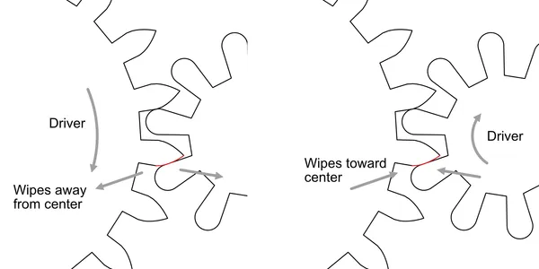
In the diagram above, note the highlighted tooth contact region. As the gears turn, there is a rolling action, but there is also a certain amount of sliding or wiping action along the contacting edges of the teeth. This is true for all gear profile types, and is obviously a source of friction.
If the epicycloid gear is the driver, this wiping action starts at the tangent point of the pitch circles, and wipes away from the gear centers. If the hypocycloid is the driver, the wiping motion starts before the tangent point and proceeds toward the gear centers.
Some maintain that the first case is best, because this wiping away action is intrinsically lower friction than the wiping toward action of the second case.
I’m not entirely sure about that,[1] but if you accept the argument, then for minimum friction the epicycloid gear should always be the driving member of the pair. This is true regardless of the relative tooth counts; if you are reducing speed, the epicycloid gear will be smaller than the hypocycloid gear.
It’s important to note that the gears will mesh properly and give continuous motion transfer whichever gear type you choose to be the driving gear. This friction argument is a fine point.
Installing
The add-in is available on Github. Either retrieve the code with Git, or download the zip file and unpack on your system somewhere. It’s written in Python, so it should work on any platform.
In Fusion 360, install via the Script or Add-in from Device option. After launch, a new icon will appear at the end of the Create menu in the Design workspace.
Important note: The add-in only works with Fusion 360’s Hybrid Design document style, which allows multiple components to be created within a single document.
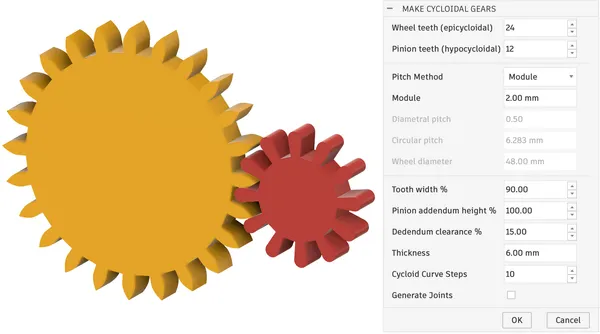
Settings
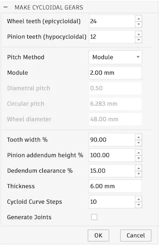
The add-in presents the above dialog. Details for each setting are below.
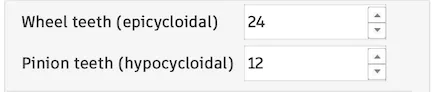
The first two fields define the tooth counts for wheel and pinion.
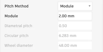
Pitch defines the size of the gear teeth. There are four supported methods for defining pitch, so, choose whichever is most familiar. They are: (Module, Diametral, Circular, or Wheel diameter). The other values will be disabled, but are computed and displayed for reference.
Module is (pitch diameter / tooth count).
Diametral Pitch is (tooth count / pitch diameter).
Important note: In most literature, the term module is used exclusively with millimeters, while diameteral pitch is used with inches. This add-in defaults to whichever matches the default units used in your document, but allows you to override.
If you select module in a document using inches, the value will be interpreted as (pitch diameter in inches / tooth count). This is not what is usually meant by the term module.
Likewise, using diametral pitch in a metric document would mean (tooth count / pitch-circle diameter in millimeters). Again this is nonstandard.
So, it might be best to stick to module if you design in millimeters and diametral pitch if you use inches.
Circular pitch is the circumference of the pitch circle divided by the number of teeth. This is a more direct measure of the tooth width, and may be a more intuitive way to visualise the tooth size.
Finally, the wheel diameter may be entered directly. (The pinion diameter is computed from wheel diameter using wheel and pinion tooth counts.) The tooth size will be scaled to fit the specified number of teeth around the pitch circle. This is also useful if you need to design a gear pair to fit a prescribed shaft spacing.
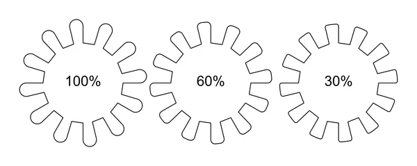
This setting allows for adding clearance between the teeth. 100% gives the theoretical maximum size (no clearance). Lower values shrink the angle spanned by the addendum. The space between the teeth is expanded by a corresponding amount, so that the pitch remains unchanged.
High values may cause excessive friction or prevent the gears from meshing at all due to inevitable imperfections in manufacture.
Low values will increase backlash. Backlash is undesirable in some cases, like CNC machines or measuring tools, but in most cases less insignificant. In clocks it has no impact at all, since they turn in only one direction.
Tooth width also affects the addendum height—narrower teeth will be slightly shorter. Note that the gear mounting distance should not be altered! To adjust radial clearance use the dedendum clearance option instead.
As mentioned above,pinion addendum and wheel dedendum do not participate in the conjugate motion of cycloidal gears; theoretically they never make contact. Since manufacturing is imperfect, they are still required, but we have some flexibility as to their form and size. The value is interpreted as follows:
At 100% height the addendum is a single arc, tangent to the neighboring dedendum faces.
At < 100%, the addendum is constructed of three arcs; the outer two tangent to the dedendum faces; the central one tangent to the outer two, and centered at the center of the pitch circle. This gives a flattened appearance yet still provides a smooth transition to the dedendum faces. I recommend at least 30% for large pinions; 100% for small.
The dedenda will be made as deep as the addenda of the mating teeth plus a small clearance value.
The clearance is computed as a percentage of wheel or pinion addendum height, whichever is larger. The same value is then applied to both wheel and pinion to make the gaps consistent.
This is the thickness of the gear extrusion; both wheel and pinion are made the same thickness.
The number of line segments used to approximate the epicycloid curve. Higher values will give a more faithful shape, but the complexity of the document rises quickly, and can impact performance. Unless your gear teeth are very large and/or your manufacturing method is extremely high-resolution, you should probably leave this value alone.
If checked, the add-in will create a revolute joint for each gear and a motion link between them. These can be used to closely examine the gear motion.
Document Element Details
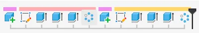
The add-in creates a component for each gear. Each component contains five entries in the timeline: a sketch, three extrudes, and a circular pattern. To make a change that’s supported by the add-in, it’s easiest to delete the components and re-run the add-in. To make a non-standard modification, you may want to edit the features created by the add-in, so it’s important to understand them.

The sketches each contain the pitch circle, a single tooth addendum, and a single dedendum. The cycloidal curve of the wheel addendum is approximated by line segments.
The three extrude features create the disk, the addendum, and the dedendum (which is a cut operation). The latter two are then duplicated in a circular pattern.
Editing
Hubs, spokes, and all the other details that make a complete gear take a variety of forms, so the add-in does not address them. Simply edit the component like any other, adding sketches and other features.
To change the number of teeth, pitch, or any property that the add-in does control, it’s easiest to delete the components and re-run the add-in. Gear thickness is an exception: simply edit the extrusions and enter the new value.
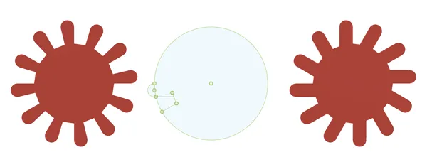
A few alterations may be made to the sketch, but you have to know what you’re doing. In the example shown above, we’ll modify the pinion tooth profile to make the pinion teeth thicker at the expense of limiting them to a single direction. This shape may work better with a 3D printer.
Open the pinion sketch. Note that it contains no constraints or dimensions, so first select everything and apply the fix constraint. This way we won’t accidentally bump something out of position.
Next, convert the leading dedendum line to a construction line. Add a new horizontal line starting on the addendum arc and ending on the lower line of the addendum. Apply tangent constraint as shown and close the sketch.
Your pinion should now look like the version on the right. Note that the pinion teeth are of uniform width. This is similar in spirit to Steve Peterson’s perfect print gears,[2] but still meshes with an ordinary cycloidal gear.
This gear gear will now operate in only in one direction: If the pinion is driven, it must turn counterclockwise; if driving, it must turn clockwise. This way, the modified tooth face will not come into play. For some devices this of limitation would not be acceptable, but for a clock it’s fine.
The Source Code
If you want to customise, this add-in is open-source and available on Github. It’s written entirely by me, starting with the template emitted by Fusion 360. No AI was used. I spent little time cleaning it up, but I do liberally comment my code.
Good luck with it!
Further Reading
Gears for Small Mechanisms, by W.O. Davis is the best book I’ve found on the subject. I think it’s certainly worth the price, but if you’re not sure, an electronic version may be borrowed at Archive.org.
Hugh Sparks has written a great page covering the geometry of the tooth form, as well as the simplified profile described in BS 978 (below).
Richard Thoen has contributed a terrific article to Hugh Sparks’ page disputing many of the claims made by proponents of cycloidal gears.
British Standard 978 part 2 is one of the documents referenced by Hugh Sparks above, and offers one method for approximating the epcycloid curve with an arc. Gears for Small Mechanisms is a better place to start, but this five-page extract serves as a handy reference, once you’re famlilar with the subject. Note that the gears produced by this add-in do not comply with BS 978 or any other published standard.
Steve Peterson designs and makes 3d-printable clocks. His designs are on MyMiniFactory for a reasonable price. I recently built his SP13 clock, and highly recommend it. It went together easily, keeps very good time, and only needs winding once a week. I’ve posted a few notes on Steve’s Blog, if you’d like to read more about that experience.
Clock Design Guidelines is an e-book written by Steve. It focuses on issues that are unique to 3D printing, but anyone curious about clocks and other geared mechanisms will enjoy it.