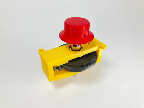
Arcade Spinner
I’m making an Arcade game! I made one about twenty years ago, but gave it away as a gift. Now I have the bug again. If you didn’t even know this was possible, search for “DIY arcade game” to learn all about it.
This time around, I’ve decided I to add a spinner control, as used in classic games like Tempest and Arkanoid.
This project was adapted to fit components that I already had on hand, so it cost me nothing. Before deciding to build, go through the bill of materials below and figure out what your cost will be. Then, bear in mind that spinners can be had for between $50 and $100. Mine works great, but I don’t know whether it’s better or worse than the commercial offerings.
How It Works
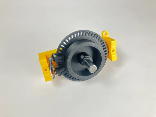
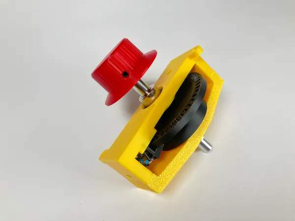
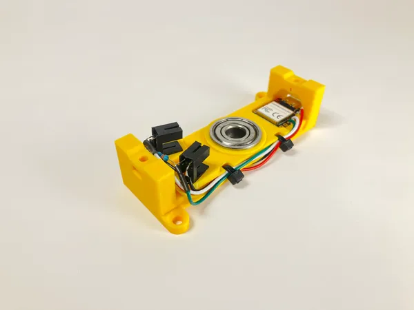
The spinner is a quadrature encoder. The knob is connected to a disc with slots near it’s edge. The disc intersects the beams of two photointerrupters situated at the perimeter of the disc and mounted offset by half of one slot’s width. The microcontroller reads the pulses from these to determine which way the knob is turning. It then mimics a USB mouse, moving in just the X dimension. The code is quite simple and thoroughly commented.
It uses the same Seeed Studio XIAO board I used in my MIDI Foot Controller project. It’s tiny, powerful, cheap, and easy to use.
Bill of Materials
In addition to the printed parts you’ll need:
| Category | Quantity | Item |
|---|---|---|
| Electronics | 1 | Seeed Studio XIAO, SAMD21 version |
| 2 | ITR9608 photointerrupters | |
| 2 | 3.3K resistors | |
| 2 | 330Ω resistors | |
| ≈50cm | 28awg or similar wire | |
| Hardware | 2 | 608zz ball bearings |
| 80mm | of 8mm steel shaft | |
| 2 | locking collars for 8mm shaft | |
| 2 | #6 x 3/4" wood screws for mounting | |
| 2 | 3mm zip ties | |
| ≈5 | 1/2" fender washers (optional; see below) | |
| Metric Fasteners | 2 | m3 x 16 screws |
| 3 | m3 nuts | |
| 1 | m3 x 6mm setscrew | |
| 1 | m2 x 4mm setscrew (see below) | |
| 1 | m2 nut | |
| misc | Cyanoacrylate glue | |
| Hot glue | ||
| Solder |
Tools / Materials
- Rotary tool
- Soldering iron
- Hot glue gun
- Computer and USB cable (to program the XIAO)
- A 3d printer of course
Printing
I used PLA for all printed parts, with 3 perimeter layers and 15% infill. All mesh files are in the correct orientation for printing. No support material is required.
The 3D models are available at: Printables, Thingiverse, or Github.
The encoder wheel is the most crucial print to get right. When slicing take care that no additional gaps appear between the slots or at the corners of the slots. I found the Arachne wall generator option to be problematic and had to use the Classic setting in OrcaSlicer.
Also, carefully tune to avoid any “elephant foot” that might change the size of the slots. Trimming afterward is likely to introduce even more errors unless you’re extremely careful.
The cavities for the photointerrupters are carefully arranged to ensure the correct angle with respect to the encoder wheel. Again, if you must trim for proper fit, be careful not to disturb this angle. The original fusion model makes use of clearance variables as discussed in my South Pointing Chariot project. It might be better to adjust these variables and reprint than to trim the piece to fit.
Prepare the Bearings and Shaft
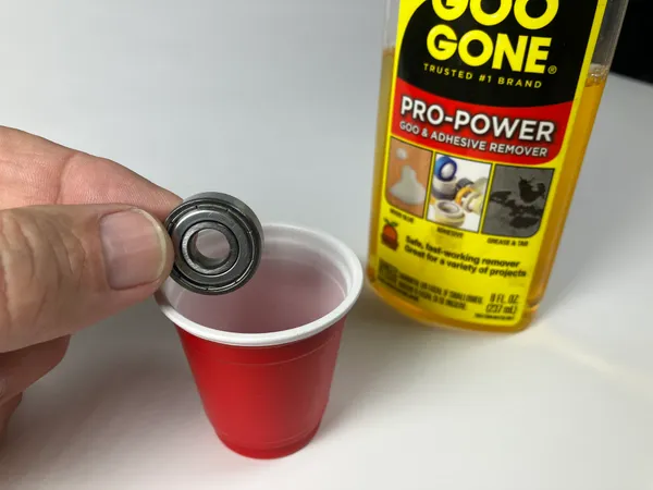
The bearings I had on hand were lubricated with some thick grease that prevented free spinning, and are a sealed type that cannot be disassembled for cleaning. I degreased them simply soaking them in a little cup of Goo Gone. I’m not sure that’s the best product for the job, but it seems to work. Whatever you use, clean it off thoroughly in case it might attack the plastic.
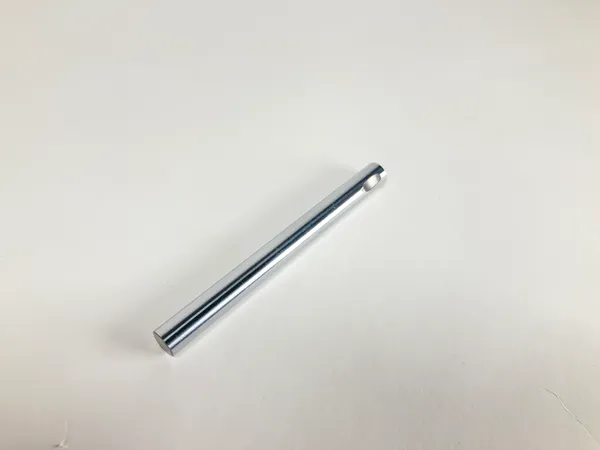
You can’t cut the shaft to length with an ordinary hacksaw; it’s hardened steel. I used my rotary tool along with my rotary tool fixture.
The set screws on both the knob and the encoder wheel should rest in a notch cut into the shaft. Again, I used my fixture. Don’t be tempted to skip this step! Without the notch, you’ll have to turn the set screw so tight that it deforms the plastic. The metal locking collars do not need such a notch.
Assembly
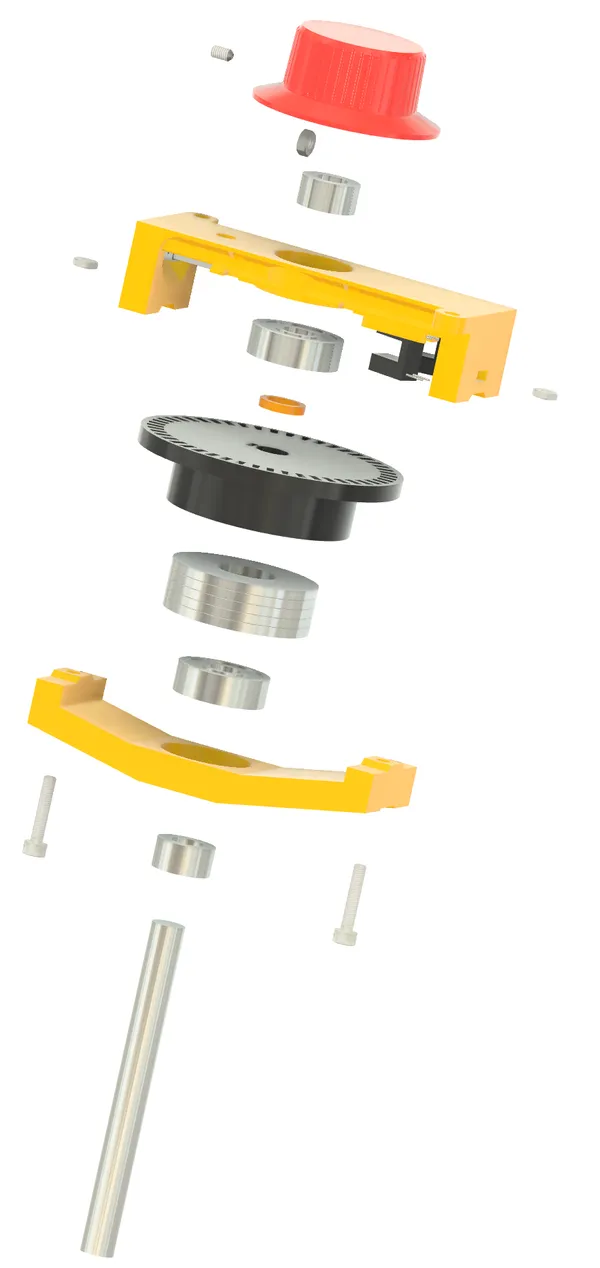
I recommend a trial assembly to ensure that everything fits without binding; then disassemble again to solder and install the electronics.
In my case, the encoder wheel was such a good fit I found the set screw to be unnecessary.
The fender washers are optional. Don’t add them until you try the device out. I did not use them in the end. They’re a loose fit, and must be secured with a bit of hot glue. You could probably substitute some lead shot.
The washers I planned for are nominally 1/2" bore by 1 3/8" OD. I think they’re the ones in this link, but I can’t remember exactly where I got them. They actually measure: 1.378" OD, .572" ID, .088" thick; (14.5mm ID, 34.9mm OD, 2.25mm thick).
About the Circuit
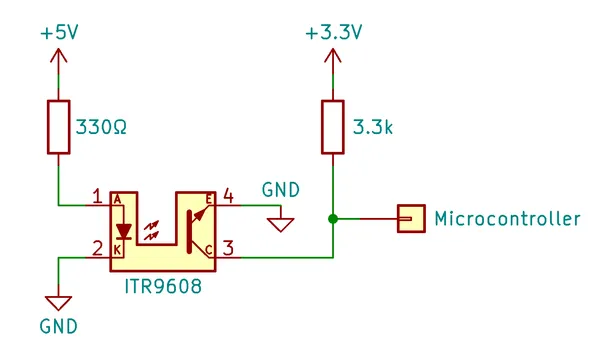
This is just half of the circuit; you need two of everything except the microcontroller board. I used the +5v supply for the LEDs just to avoid overtaxing the regulator on the XIAO board. The input pins require +3.3V.
The pull-up resistor value was determined by observing the waveform on an oscilloscope. Pull-up/down resistors are often 10k or higher when used with one-shot inputs like push buttons. I found that this application required a much stiffer pull-up to get an acceptably square wave at normal spinning speeds. The best choice turned out to be about 3.3k.
The LED is rated at 50mA max, but I suspected that it would work at much less, and started my testing at 25mA. Since the rated forward voltage drop is 1.2V, the current formula is:
The following standard E series resistors give approximate currents as shown:
| Resistor | Current |
|---|---|
| 150Ω | 25mA |
| 180Ω | 21mA |
| 220Ω | 17mA |
| 270Ω | 14mA |
| 330Ω | 12mA |
| 680Ω | 6mA |
Testing showed very reliable performance down to 12mA with just very slight degradation starting at 6mA. I settled on 330Ω.
Install and Solder the Electronics
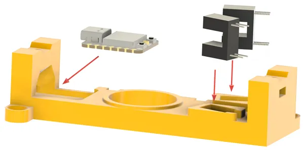
The photointerrupters should be a snug fit in their mounting holes. The holes precisely position the sensors at the correct angle, so be careful if you have to enlarge them with a knife; it might be better to adjust the clearance value in the original Fusion 360 model and re-export.

I soldered the resistors directly to the photointerrupters. This animation illustrates the sequence I followed. The LED side of the photointerrupters is situated at the bottom.
Gather your patience first; this is a fiddly job!
I used heat shrink wherever I could, but there are still a few bare leads. Obviously, these must not touch each other when complete. This sounds like a problem but it really isn’t. Once the wires are all soldered and secured with zip ties, everything’s stiff enough to remain in place.
The wire color scheme used in the illustration and my prototype is:
| Color | Use |
|---|---|
| Black | Ground |
| Red | +5V |
| Yellow | +3.3V |
| Green | XIAO pin 9 |
| White | XIAO pin 10 |
After everything’s fitted, put a small drop of CA glue on the photointerrupters to fix them in place if necessary.
Solder the wires into the XIAO board and program it before securing the XIAO board to the frame. Once all is well, a very small dab of hot glue beneath the XIAO board might be necessary to keep it in place. In my case, a friction fit was enough. The hole in the frame beneath the XIAO allows you to press it back out if necessary.
When all’s complete; secure the wires in their channel with two zip ties, taking care that they do not rub on the encoder wheel.
Programming
Firmware source is at Github.
I use PlatformIO, but the Arduino IDE will work too. You’ll need the to set the board to the Seeed studio SAMD21 XIAO, and include the Mouse library.
After programming, your computer will think your spinner is a mouse. Turning the knob should move the mouse pointer horizontally. If it moves the wrong direction or too slowly, adjust the SCALE definition and recompile. The default scale is -2, simply because that’s what worked for me. You will probably also have to calibrate the arcade emulator.
The spinner should work with any emulation software; it’s up to you to figure out the details. I use AdvanceMAME, and found this old but still helpful post. I also found that the Raspberry PI was not polling the mouse frequently enough for smooth operation. Tuning the usbhid.mousepoll parameter in cmdline.txt did the trick.
Mounting
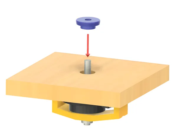
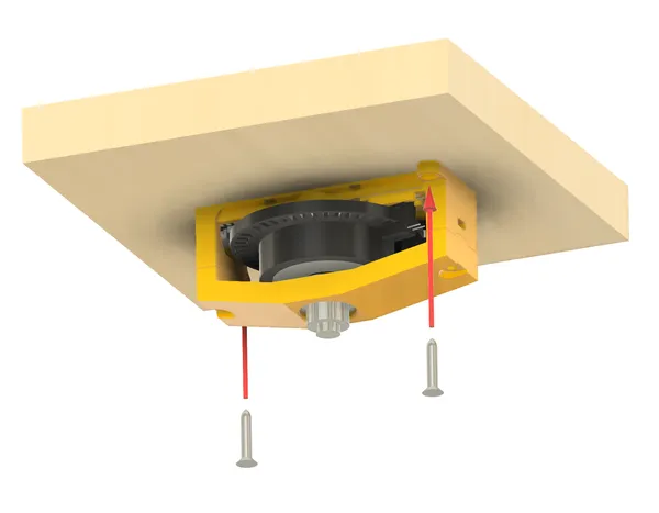
I opted to mount the spinner from the bottom of the panel, which keeps the top of the panel clean and allows for different panel thicknesses. The hole must be large enough to accommodate the locking collar, plus a bit of breathing room. The included alignment tool slips over the shaft and into a 3/4" (19mm) hole. This keeps the spinner aligned while you drill the pilot holes for the mounting screws. As my panel will be 3/4" thick, I’ll use two 3/4" x #6 screws.
Taking It Further
Higher Resolution?
The correct placement of the photointerrupters depends on the the encoder wheel. If you’d like to change the encoder wheel size or slot count, see the Encoder Planning sketch and the related parameters in the Fusion 360 document.
But before getting too carried away, know that my first prototype used a larger 72 slot wheel simply because that’s what the original Tempest spinner used. While it worked, it was just a bit too big to fit in my planned panel, and the larger wheel was more prone to warp and wobble.
This one has just 48 slots, and I cannot tell the difference. Note that in the quadrature scheme we actually get four times as many events as there are slots, so there’s still plenty of resolution.
I did not experiment with smaller slots. In retrospect, I think my printer could handle it. If you want higher resolution, I recommend you try smaller slots (and thus more of them) before increasing the wheel size.
Two spinners
It’s possible to wire two spinners to the same microcontroller. This will require corresponding changes to the code, but it should be straightforward job. One will be the X axis and the other the Y axis of the mouse.
Different Microcontroller
I’m sure the project could be adapted to other microcontroller boards. It must have a USB port and support for the Mouse library. Of course, you’ll have to adapt the mounting arrangement.
Good luck with the project! If you build your own, please post a photo at Printables or Thingiverse!